State of the BMS Software
Development of the BMS software, including capturing of software system specifications, software architecture and design, implementation, and initial validation took place by Collin Bolles. This document details the state of the software as of 5/13/2022 and is intended as a reference for the next developer to take up the BMS project. The remainder of the document will go over the current software architecture, important implementation details, notable pitfalls, and what remains of the project.
Introduction
As stated elsewhere in the BMS documentation. The BMS system is built around the BQ76952 which is a battery management chip created by TI. Much of the software architecture is designed around the functionality of the BQ chip and thus an understanding of the chip is necessary to understand the implementation details of the software. Documentation for the BQ76952 can be found on TI’s website.
Additionally, the BMS system from a software perspective is made up of a STM32f334 for the microcontroller, an EEPROM module for non-volatile memory, and a CAN transceiver for network communication. These are the main components that the software interacts with and the usage of each element is discussed in details further on.
Currently, the software is in a state where the basic requirements for the system are met. Essential communication with the BQ has been implemented, an ability to store and transfer settings is enabled, and communication on the CAN network is possible. Additional validation is still required before the software is considered validated for continuous use on the motorcycle system. The currently supported features, summary of currently validated software, and the features still needed to be added are detailed below.
High Level Features
A full indepth description of the system requirements are detailed in the Software Requirement Specification (SRS) which can be found here. Some of the key details are listed below as they have the biggest impact on the software.
Transfer and storage of BQ settings
Sharing of battery pack data over CANopen
Control of current flow into/out of battery pack.
These key requirements dictate how the software is designed and constrained. An overview of each and how the software as impacted based on the requirements are included below.
Transfer and Storage of BQ Settings
The BQ chip is designed to be able to be used in a wide range of battery systems and as such has a lot of settings which control the functionality of the chip. In total there are about 274 settings which control everything from information on the battery pack itself, to fault handling cases, to communication protocol settings. These settings are set mostly by the Electrical team as they have the most domain knowledge in that area.
BQ Settings Overview
The BQ supports two main ways of getting the settings into the BQ’s memory. The first approach is through a method called OTP (one time programming) where the BQ is placed in a special state and the settings are written into non-volatile memory. The issue which this approach, as the name suggests, this can only be done once. As the documentation states “once a bit is set to a 1, it cannot be set back to a 0”. As we have a need to tweak settings as we learn more and make changed to the system we cannot rely on OTP.
The second approach, and the method we use, is to transfer the settings to the BQ on system startup. Each setting can be written to the BQ via I2C commands so when the system starts up, the STM writes each setting to the BQ. The benefit of this approach is that we can change the settings as need be, but the downside is the need to store all the settings and transfer the settings to the BQ each time the system starts up. This means that the settings have to be stored in some non-volatile memory, and that the BMS system needs some method to allow for the settings to be transferred from some host system to the STM.
Transfer of Settings to BMS System
There needs to be an approach to get the settings transferred from some host
to the BMS system. This is handled via CANopen which allows for transfer of
larger portions of data via a method called “block transfer”. The code for
handling the transfer logic can be found in BQSettingStorage.
The BQSettingStorage class handles the logic of exposing the setting
transfer and storage logic. It has two main responsibilities. First, the
class contains the logic of exposing a means to transfer the settings from the
host to the BMS system over CANopen. Second, the class handles reading and
writing those settings between non-volatle memory (EEPROM) to the BQ chip
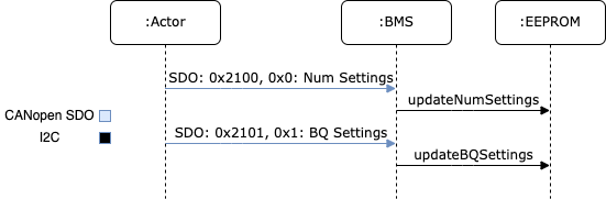
itself. The transfer of the settings take place across two steps. First
the external host writes the new number of settings to the BMS system over
CANopen. Second, the external host then writes out each setting over
CANopen. The BQSettingStorage handles the whole process of updating the
number of settings and getting the settings themselves into EEPROM. Below is a
small sequence diagram showing what takes place to allow the settings to be
transferred.
The exposure of these settings is handled via CANopen stack, so for a more indepth understanding of how to implement custom settings you can refer to CANopen stack’s documentation.
Converting BQStudio Settings to Binary
The BQ settings are usually set using a TI provided software, BQStudio, and then exported to a CSV format. The CSV format stores a number of pieces of information including the location in the BQ where the setting should be stored, how many bytes the setting takes up, a human readable representation of the data, and an equation to convert the human readable format into what can actually be stored in the BQ. These settings needs to be converted from the CSV into a binary file which can then be transferred over CANopen. For more information on how the data is packed into a binary format, refer to the setting transfer documentation. The backed format in that document is how the settings are stored both for transfer over CANopen and for storage in EEPROM.
A python script is provided which handles the logic of converting the CSV into a binary format and another script exists for the logic to transfer the binary file over CANopen. Documentation for how to use those scripts are included with the scripts. Luckily the process of sending a binary file over CANopen is a standard practice, so the binary file can be transferred with any tool capable of CANopen including a Vector CAN adapter.
The scripts to convert the CSV and transfer the CSV over CANopen can be found
in tools/bqsettings/. The usage of the scripts are further explained there.
Transfer of Settings to BQ
When the BMS system starts up, the STM reads the number of settings from EEPROM and transfers that number of settings from EEPROM to the BQ over I2C. These settings are transferred one-by-one until all have been sent across. This takes place over a 30-45 second period.
Sharing of Battery Pack data Over CANopen
The battery pack information is exposed over CANopen via the object dictionary. Most of the data is polled from the BQ over I2C at some interval and a pointer to that data is included in the CANopen objection dictionary. This sharing of data is highly standard and does not have BMS specific logic. The currently supported data which is exposed is listed below.
Total battery pack voltage
Individual cell voltage
Current state of the BMS (based on the BMS state machine)
Information on the state of cell balancing
Some information which is not yet exposed but should be is listed below.
Temperature readings
Number of BQ settings stored
Ability to read back stored BQ settings
Misc BQ status
Control of Current Flow In/Out of Battery Pack
Current control is indirectly handled via a status pin which represents if the BMS is in an “OK” state to charge/discharge. Currently the software has that pin as a GPIO of the STM, however, this is not really the case in hardware. In hardware the status pin is really connected to, and controlled by, the BQ chip. As such, the firmware will need to be updated to control the “OK” status through the BQ chip.
System State Machine
The software is designed around the requirements expressed above. The whole system is implemented explicitly as a state machine which reflects the actions taking place in the BMS system. The state machine is listed below. Additional details regarding implementation will follow.

The first part of the state machine from “Transfer Successful” and above reflects the settings transfer logic. The “Factory Init” state represents when the BMS system is waiting for settings from a host and the “Transfer Settings” state represents when the STM is actively reading settings from EEPROM and sending those settings over to the BQ.
The remainder of the state machine represents the normal sequence of states that takes place when the system is powered on. The system makes health checks and determines what the battery pack is connected to to determine what functionality takes place.
The STM determines what that battery pack is connected to by watching for
specific CANopen heart beats. The SystemDetect class handles this by
processing incoming heart beats and determining the origin of the heart beat.
If the heart beat matches the pre-charge board, the system the battery pack
is connected to is identified as the motorcycle. Alternatively, if the heart
beat is found to be the charge control board, the system is identified as
being the charger. Additionally, a timeout is in place to represent if no
known system is detected if a heat beat is not received within a specific
timeout.
Health checks also take place throughout the state machine. These health checks mainly consist of reading the state of an alert GPIO. The alert GPIO is a GPIO that directly connects to the BQ chip. The BQ chip is configured to produce an alert which certain dangerous conditions are met by the battery pack.
The interlock is the last main portion which controls the flow of the state machine. The interlock is used to identify when the battery pack is actually plugged into something. This is handled via a GPIO to the STM.
Code Breakdown
This section is dedicated to explaining the purpose of each class in the code base. The goal being that a reader will be able to understand the purpose, and where to go to look for specific functionality.
BMS
The BMS class is the top level class which represents the BMS system. Its main purpose is to contain the CANopen object dictionary and handle the logic of the state machine. Contained in the code base is the object dictionary itself, and the logic which is executed within each state and the logic for handling state transitions. These functions reach out to the other components of the BMS system.
BMSLogger
This is a utility for logging in the BMS. This was created before logging
was added to EVT-core. This is no longer needed and the code base can be
updated to use EVT-core’s logging logic instead of this BMSLogger.
BQSetting
This class represents a single BQ setting. This has getters/setters to
represent each aspect of a BQ setting such as the address, setting type,
number of bytes, and the data itself. The BQ setting also has the ability to
encode and decode settings from the binary format documented above. This is
used as the means of representing a setting in the BMS system and as such is
used heavily by the BQ76952 class and the BQSettingStorage class.
BQSettingStorage
The BQSettingStorage handles the transfer and storage of BQ settings. This
class handles the transfer of settings from a host to the BMS system via
CANopen, handles saving the settings into EEPROM, and handles sending settings
from EEPROM to the BQ itself.
dev/BQ76952
This is the representation of the BQ chip itself. Contains is a series of functions which expose the functionality of the chip itself. This includes features such as saving a setting, reading voltage, balancing cells, etc. As more features of the BQ chip are supported, this class will grow the most.
dev/Interlock
The Interlock is a representation of the interlock and is really just a
thin wrapper around a GPIO which adds some semantics in the interlock usage.
dev/SystemDetect
The system detect handles the logic of determining what the BMS is connected to. This differentiates between the CANopen heart beat of the pre-charge vs. charge controller.
Targets
Several targets are provided as well which handle different functionality. Each one is listed below.
BMS
This is the main target and the one that sets up the state machine and full exposure of information over CANopen. This is what is flashed to a working board.
bq_interface
This is a UART utility that adds the ability to interface with the BQ via the STM in a UART environment. The user has a menu which they can use to read/write settings, poll voltage, and even enable/disable balancing of cells. This is a great tool for debugging issues specifically with the BQ.
bq_settings
This is a test target for the settings themselves. It is used for verifying that the settings can be encoded and decoded into their binary format correctly.
eeprom_dump
As the name suggests, this utility is for looking at the contents of EEPROM. All of the settings are read from EEPROM and printed one-by-one.
setting_transfer
This target is used specifically for testing the setting transfer from EEPROM to the BQ. This is useful when testing to make sure each setting is transferred as expected.
system_detect
This utility is used for testing the ability of the BMS system to identify what external system it is connected to
setting_transfer
This target is used specifically for testing the setting transfer from EEPROM to the BQ. This is useful when testing to make sure each setting is transferred as expected.
system_detect
This utility is used for testing the ability of the BMS system to identify what external system it is connected to.
Current State of Features
Transfer of Settings
The ability to transfer settings is nearly complete. The last part which has become more critical with the EVM broken is the need to poll the current settings from the BQ.
Currently the whole process for transferring the settings, storing the settings in EEPROM, and sending the settings to the BQ is supported. This is all that is required assuming the settings are converted to a binary format correctly and that the settings provided in the CSV format are correct.
However, for additional testing both software wise and electrically, there is a need for the ability to read back the settings and potentially write individual settings when the system is run. This feature set has not been worked on but will be needed now that the EVM is no longer functioning. Preliminary discussion on implementation has taken place and has boiled down to two main aspects.
First, the ability to poll arbitrary settings over CANopen. This would involve allowing a host to poll BQ settings using CANopen requesting a set number of bytes from a address in the BQ. The second aspect would be a corresponding python script which would be capable of reading back all of the BQ settings corresponding to the BQStudio produced CSV to verify that the settings match what was expected.
This is no small undertaking, but the infrastructure exists with the ability
to represent setting using the BQSetting class and the ability access
certain pieces of data over CANopen already implemented.
BMS OK Status
The general logic to represent that the BMS is in state ready to charge/discharge is in place, but needs to be updated to have the control be on the BQ side rather then the STM side. Currently, the STM controls this functionality via a GPIO on the STM itself, however this needs to be changed to instead interact through the BQ chip. Additional details would be available from the electrical team.
Exposure of Data
The basic ability to poll voltage data is available, but additional data should be exposed as well. First would be temperature data. The BMS system has the same ADC MUX implementation as the TMS and as such can use similar firmware to poll the temperature data and expose that data over CANopen.
Additional status data should also be exposed. For example, a “status” register is alluded to in the code documentation which refers to the idea that a value should be exposed over CANopen which has a bitmap representing the state of the system. The goal of this “status register” would be that it stores information on system health and can also be checked by an external system when something goes wrong for easier debugging.
Deep Sleep
A deep sleep mode needs to be added to the BMS. The BMS system is intended to essentially be always powered on since the BMS is powered by the battery pack itself. As such, during periods of battery storage, the system should enter some deep sleep mode to not draw too much power. The intention would be that the system makes use of an ST specific deep sleep mode and awakes under some IO condition. This could be through a GPIO wakeup which as the interlock detection, or potentially a wake up over CAN setup.