Software Requirements Specification for DEV1 Battery Management System
Introduction
Purpose
The purpose of this document is to detail the software requirements and constraints for the firmware of the Dirt Electric Vehicle Battery Management System (DEV1 BMS). This document will go into detail on the requirements necessary for the system as well as detailing the constraints that the system will be under. The intention is that this document will provide a means to holistically express the needs to the DEV1 BMS system.
Document Conventions
This document was created based on the IEEE template for software requirements specifications. As such it will mainly adhere to the verbage and style set by IEEE convention. Additionally, a glossary has been provided in the Appendix which covers common phrases that will be used in this document.
Intended Audience and Reading Suggestions
The intention is that this document will be accessible across engineering disciplines. The DEV1 BMS represents a highly inter-disciplinary project on the RIT Electric Vehicle Team and as such this document should be accessible to all involved. Below is a break down of the intended audiences and how they may use the document. This list is not exhaustive, but intended to guide common readers of this document.
Electrical Team Members: Members of the electrical team who are designing and building the DEV1 BMS. Members of this group may refer to this document to ensure requirements and constraints align with their expectations. Additionally, this document can be used as a point of reference during the hardware/firmware bring up and debugging.
Firmware Team Members: Developers on the firmware team who are designing, developing, and testing the DEV1 BMS firmware. Members of this team will need to refer to this document throughout the development process to ensure all target needs are met within the agreed upon constraints.
Integration Team Members: RIT EVT team members who handle systems level integration on the team. These team members may use this document to gain and understanding of how the DEV1 BMS will operate. Most critically, how the DEV1 BMS will operate within the structure of the DEV1 architecture.
The document is laid out where it is not strictly necessary to read all sections in their entirety. Instead each section should be self-contained and self-entirety within its scope. As such audience members are encouraged to read the sections that most pertain to their needs. Additionally, the glossary in the Appendix may prove useful in situations where phrases may be used in specific ways within this document.
Product Scope
The DEV1 BMS handles the battery management of the system. The DEV1 BMS will interact directly with the twin battery packs that will be present in the DEV1 architecture. As such, the DEV1 BMS scope will include battery pack health and safety, sharing battery statistics on the DEV1 CAN network, handling cell balancing, and providing a general interface to the battery packs. A noteworthy exclusion to the scope is the power distribution logic which will not be handled by the DEV1 BMS. The power distribution is not in the scope of the DEV1 BMS and instead is handled by the DEV1 APM.
Safety
The DEV1 BMS will handle safety critical functionality that relates to the health of the battery pack. These range in levels from low priority to safety critical events. Below are the features that fall under the scope of the safety aspect of the DEV1 BMS.
Control of the flow of current
Notification of thermal issues
Notification of cell voltage issues
Notification of BQ76952 state
Detection of battery connector
Diagnostics
The DEV1 BMS will be the main point-of-contact with the battery pack and the cells contained and as such will have to have functionality to extract information on the battery pack itself. Functionality that falls under this scope is not safety critical and is intended to be used for data collection and decision making during the usage of the motorcycle. This information will be exposed on the CAN network and the DEV1 BMS will also expose means of directly requesting data from the BQ76952 battery monitoring IC.
Transmission of thermal state of battery pack
Transmission of battery pack voltage
Transmission of average cell voltage
Transmission of standard deviation of cell voltage
Exposure of BQ76952 chip
Charging
The charging of the battery pack will have health checks that are managed by the DEV1 BMS. After charging takes place, the DEV1 BMS will also oversee cell balancing that will take place within the battery pack. As such, the following features will need to be included.
Performance of handshake with charge controller
Reporting of health of battery pack
Control of the flow of current
Overview
The rest of this software design document will go further into the specifics of the requirements while also looking at the constraints of the system. The goal is to clarify the use cases of the DEV1 BMS and specifying what the DEV1 BMS will do in those use cases. Design considerations will not be discussed, however notable design constraints will be covered.
Overall Description
Product Perspective
The DEV1 motorcycle will make use of custom battery packs which will provide power to the entirety of the DEV1 architecture during normal operation. The target event for the DEV1 motorcycle is a 24 hour endurance race. With these considerations in mind, the DEV1 BMS is critical to the success and safety of the DEV1 project. A critical component is the safety of the battery cells within the battery packs. As such, the DEV1 BMS will need to perform safety checks and handle the battery cell balancing logic.
The DEV1 BMS will be a board that will be present in each battery pack. Each DEV1 BMS will operate independently and will handle the safety of the individual pack. This includes both during normal operation when the pack is on the motorcycle as well as when the pack is being charged.
The DEV1 BMS itself is made up of two major configurable components. The ST microcontroller which handles programmable logic and exposes the DEV1 BMS on the CANopen network. As well as the BQ76952 battery monitor and protector IC which handles the battery safety and monitoring logic.
User Interfaces
Users will rarely interact directly with the DEV1 BMS software. The DEV1 BMS software will mainly be interfaced with via CANopen and thus will require additional tools to interact with the DEV1 BMS. An external tool will be needed to interact with the DEV1 BMS and will not be in the scope of the DEV1 BMS software.
Hardware Interfaces
The DEV1 BMS will be exposed on the CANopen network which is made up of a two-wire differential pair. The connector will be standardized and be handled by the DEV1 system team. The software on the ST microcontroller will be connected directly to the I2C lines of the BQ76952 chip.
Software Interfaces
The main software interface will be the expose of the BQ76952 chip over the CAN network. The DEV1 BMS will need a software interface for acting as a bridge between the external actor and the BQ76952 chip. The DEV1 BMS will need to be flexible to expose all functionality of the BQ76952 so that the BQ76952 can be configured.
Communication Interfaces
The main communication interface for the DEV1 BMS will be CANopen. CANopen is build on top of the hardware and data layer specifications of CAN. The majority of the CAN based network communication that will be used will conform to CANopen including how the DEV1 BMS will expose information on the DEV1 system network. The BQ76952 chip expose logic may or may not conform to CANopen depending on the final implementation.
Communication between the ST microcontroller and the BQ7695 will be handled via I2C. The BQ7695 contains the specifications of the I2C interface.
Memory Constraints
The produced software is limited to the 64KB of flash memory that is available on the STM32F302r8. Therefore the resulting binary must fit within this size.
Operations
The DEV1 BMS will operate in four main states during operation. The main output from the states is the current flow control. When flow is enabled, current is able to flow into and out of the battery, when flow is disabled, current cannot flow. The interlock positioned on the battery connector is what triggers the initial mode transition on system startup. The diagram below follows the logic that will need to be implemented.
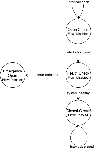
Note, when an critical error takes place, the system cannot directly recover from the error. This is done intentially. The reasoning is that if a critical error takes place with the battery pack the system should first be manually inspected and probed for the issue. Then after the issue is resolved, the system can be power cycled restarting the state machine logic.
Site Adaptation
The DEV1 BMS is intended specifically for the DEV1 system. Therefore, the software requirements and design will center around the specifics of the DEV1 system. No additional adaptations are currently being considered.
Product Functions
Safety
Control of the Flow of Current
The DEV1 BMS will need the ability to control the flow of current into and out of the battery pack. This will be a shutoff that will stop the flow of charge that will be used both during normal operation and during safety critical events. As such, the DEV1 BMS will need a programmable means to control that flow so that the system can respond to a range of stimuli. Below are listed out the situations that could cause the DEV1 BMS to stop the flow of current.
Thermal situation where battery pack as passed a configurable threshold temperature
Interlock does not detect the presence of a battery connector
BQ76952 chip has detected one of many configurable safety critical events such as a thermal runaway event
Notification of Thermal Issues
The DEV1 BMS will contain temperature sensing units. These units will be used both for determining if a thermal safety critical event has taken place as well as for notification to the greater DEV1 system of the current thermal situation of the battery pack. This is intended for providing a means for the DEV1 thermal management system to determine the amount of heat energy that will need to be removed from the battery pack and to plan accordingly. The notification process will take place via the CANopen network which will be discussed in greater detail in the section “External Interface Requirements”.
Notification of Cell Voltage Issues
The DEV1 battery pack will need to have constant health check on the state-of-charge of the cells. As such, the DEV1 BMS will handle collecting and broadcasting the state of the cell voltages on the CANopen network so that other systems can respond accordingly.
Notification of BQ76952 State
The BQ76952 is the IC which enables the DEV1 BMS to interact with the battery pack. As such it has the internal logic for collecting and reporting on the health of the battery pack and the cells within. The DEV1 BMS will need to expose the state of the BQ76952 on the CANopen network for safety response actions and to inform the rest of the DEV1 system on the state of the battery pack.
Detection of Battery Connector
The DEV1 battery pack is equipped with an interlock which can be used to detect the presence of a connector attached to the battery pack. Use of this interlock is critical for battery operator safety. The contact points of the battery should only be active when a valid connector is present. Otherwise, the battery contact points should not be active.
Diagnostics
Transmission of Thermal State of the Battery Pack
The DEV1 BMS will continually monitor the temperature readings from inside of the battery pack and report the temperature on the CANopen network. The temperature data will be reported at a fixed rate interval.
Transmission of Battery Pack Voltage
The DEV1 BMS will poll the battery pack to collect the voltage of the whole pack. This data will then be packaged and published on the CANopen network.
Transmission of Average Cell Voltage
The DEV1 BMS will have the ability to collect cell voltage data for sets of cells that are in series with each other. From there the average cell voltage can be estimated across the battery pack. This average should be exposed on the CANopen network for diagnostic applications.
Transmission of Standard Deviation of Cell Voltage
For safety and battery pack longevity, the cells of the battery pack should be maintained to very similar levels. The standard deviation of the cell voltages should be calculated by the DEV1 BMS and presented on the CANopen network.
Exposure of BQ76952 Chip
The BQ76952 chip is the most important component in the DEV1 BMS and is used for allowing for all abilities of the DEV1 BMS. Additionally, the BQ76952 is configured for operation externally and should thus have a means to expose the chip from the DEV1 BMS. The DEV1 BMS will have a means for the BQ76952 to be configured over the CANopen network.
Charging
Performance of Handshake with Charge Controller
The DEV1 BMS will control the flow of charge both into and out of the battery pack and as such, the DEV1 BMS must have a handshake with the Charge Controller. The DEV1 BMS will handle making a series of health checks that will follow the same logic as the “Control of the Flow of Current”. If the DEV1 BMS determines that the battery pack is in a safe state for charging, then the DEV1 BMS will notify the Charge Controller and charging can start to take place. At any time during the charging logic, the DEV1 BMS can determine as safety event has taken place and stop the flow of charge.
Reporting of Health of Battery Pack
During the charging process, the DEV1 BMS will continue to output health information on the battery pack. The data that will be sent out will follow the specifications of the “Diagnostics” section.
Control of the Flow of Current
While the charging is taking place. The DEV1 BMS will have the final decision if charge will flow. This decision will be made on safety decisions as well as the presence of the interlock detection signal. At any point during charging, if the DEV1 BMS detects a safety critical situation, the flow of current can be disabled.
User Classes and Characteristics
Those who interact with the DEV1 BMS will be expected to have a high level of understanding of the electrical system as well as having a high level of knowledge on battery safety. Human interaction with the DEV1 BMS will only take place during charging, data collection, and BQ76952 configuration. For the charging it is expected that at least one person who worked directly on DEV1 BMS design will be present.
For data collection, less technical experience will be required as safety critical systems should not be interacted with during data collection. During this time an external device can be used to collect the diagnostic messages from the DEV1 BMS.
During configuration of the BQ76952. The users who are interacting with the DEV1 BMS will need to be 1 firmware team member and 1 electrical member who worked directly on the DEV1 BMS. Since the BQ76952 is a safety critical component, a very high technical knowledge will be needed.
Operating Environments
The software will operate on the ST microcontroller present on the DEV1 BMS. The software environment is embedded with no operating system present. All development will take place through the EVT-core library and will interact directly with the ST microcontroller.
Design and Implementation Constraints
The DEV1 BMS software will exist in an embedded environment and as such, all design considerations will require the software to be runnable on an embedded system.
Additionally, for the low level interactions with the ST microcontroller, the EVT-core software library will be used. Any additional required functionality will need to be considered and added into the EVT-core library itself.
Communication with the rest of the DEV1 architecture will take place via CANopen. Design of the communication system will need to revolve around CANopen and adhere to CANopen standards.
The hardware has already been determined and the software must be designed to support the existing hardware. The microcontroller will be a STM32F302r8 chip and the battery monitor chip will be a BQ76952. Software design will revolve around the limitations of those chips.
User Documentation
Documentation will need to exist that highlight the safety logic of the DEV1 BMS. This will include a means of determining what has triggered a safety event on the DEV1 BMS. A large part of the documentation will focus on the object dictionary which is the main means of interacting on the CANopen network.
Additional documentation will need to exist for how the DEV1 BMS will expose the BQ76952. Exposure of the BQ76952 will take place over CANopen and proper documentation will need to exist for users to be able to configure the BQ76952.
Constraints
Below are some constraints worth considering. They are a fixed part of the system.
Development must be in C/C++
Communication will take place using CANopen
EVT-core will be used for low level microcontroller interfacing
Must be developed for the STM32F302r8
Battery monitoring will take place through the BQ76952
Assumptions and Dependencies
It will be assumed that all hardware will operate as designed. This includes proper communication present between the BQ76952 and the ST microcontroller. Part of the communication assumes that the BQ76952 can properly manage each of the groupings of cells in series. Another large safety based assumption is that the BQ76952 will be able to stop the flow of charge into and out of the battery pack.
Apportioning of Requirements
Not all requirements are know at this time as the DEV1 system continues to develop. These un-restricted requirements will need to be finalized before the implementation of the DEV1 BMS software.
The CAN messages to capture from the DEV1 system
Scope of emergency cases to stop flow of current from the battery pack
Specific CAN network IDs
Format of CANopen messages that the DEV1 BMS will produce for sharing data
Specific Requirements
External Interface Requirements
BQ76952 CAN Control
The BQ76952 CAN interface is an exposed ability to communicate with the BQ76952. The CAN interface will actually expose the I2C interface that the STM32F302r8 has with the BQ76952. This will limit software complexity and will ensure that all the features of the BQ76952 are correctly exposed. These messages will come across the network realistically at any point from the perspective of the DEV1 BMS, but practically these messages will be received when the battery pack is not on the motorcycle.
Read Request Message Format
Externally, a CAN message can be sent to the STM32F302r8 which will be interpreted as a request to interact with the BQ76952. Messages with a data length of 1 will be interpreted as a read request.
CAN ID Extended: 0x800
Data Length: 1
Byte |
Description |
0 |
Address of the register to read from of the BQ76952 |
Read Response Message Format
After a read request made, the ST microcontroller will respond with a response message. The response message will contain a single byte that was read from the BQ76952.
CAN ID Extended: 0x801
Data Length: 1
Byte |
Description |
0 |
Byte read from the BQ76952 |
Write Request Message Format
A request to write to the BQ76952 can also be made. Instead of a single byte, two bytes will be sent.
CAN ID Extended: 0x800
Data Length: 2
Byte |
Description |
0 |
The address of the BQ76952 to write to |
1 |
The value to write to that address |
Other Nonfunctional Requirements
Software will fit within 64KB of Flash memory
Design and development will be handled by the firmware team
Testing will take place for failure cases
Software will need to be robust enough to handle power loss
Appendix
Glossary
Term |
Definition |
APM |
Auxiliary Power Module |
BMS |
Battery Management System |
BQ76952 |
Battery monitor IC |
CAN |
Controller Area Network |
CANopen |
Communication protocol built on CAN |
DEV1 |
Dirt Electric Vehicle 1 |
EVT |
Electric Vehicle Team |
I2C |
Inter-Integrated Circuit |
KB |
Kilo-bytes |
STM32F302r8 |
ST Microcontroller selected for this project |
TMS |
Temperature Management System |
References
Revision
Revision |
Description |
Date |
1 |
Initial documentation. |
10/19/2021 |