BQ76952 Settings Transfer
The BQ settings represent the “direct commands”, “subcommands”, and RAM settings that can be sent to the BQ chip. The specifics of the how to send the settings are detailed in the BQ Software Development Guide.
The BQ settings are transferred to the STM via the CANopen and UART interfaces. The STM then saves the BQ settings into EEPROM to be loaded and sent to the BQ chip itself on startup.
Approach to Configuring the BQ
The BQ chip has two main means of loading settings. First, the settings can be programmed into the chip’s non-volatile memory through a process called OTP (one-time programming). Those settings can only be programmed in once. Below is a snippet from the BQ Technical Reference Manual:
The OTP memory in the BQ76952 device is initially all-zeros. Each bit can be left as a “0” or written to a “1,” but it cannot be written from a “1” back to a “0.” The OTP memory includes two full images of the Data Memory configuration settings. At power=up, the device will XOR each setting in the first OTP image with the corresponding setting in the second OTP image and with the default value for the corresponding setting, with the resulting value stored into the RAM register for use during operation. This allows any setting to be changed from the default value using the first image, then changed back to the default once using the second image. The OTP memory also includes a 16-bit signature, which is calculated over most of the settings and stored in OTP. When the device is powered up, it will read the OTP settings and check that the signature matches that stored, to provide robustness against bit errors in reading or corruption of the memory. If a signature error is detected, the device will boot into the default configuration (as if the OTP is cleared).
Because OTP is most reliably accomplished in a manufacturing setting and our decided settings are likely to change during testing, it was decided to not rely on OTP and instead send over the settings manually via I2C commands at system startup. This is a common practice and another recommend approach seen elsewhere in the TI documentation. For our BMS, it was decided that the BMS firmware would handle the storage of the desired settings and the programming of those settings over I2C to the BQ chip.
BQ Setting Representation
BQ Settings are made up of 7 bytes of data. Below is the break down of the data as it is represented in the byte array.
Note
CANopen stores data in little endian format, so the BQ settings mirror this to make debugging across the CANopen network easier. Settings will be read in over CANopen in little endian format, and the settings will be stored in EEPROM in little endian format. The little endian nature only impacts individual values i.e.) The address is in little endian format.
An important concept is the “type” of command. The BQ has three main functions that can be configured. First are direct commands. Direct commands are written over I2C directly to specific registers. Subcommands are indirectly written by writing the address into two registers. RAM writes are also done with this indirect method. Both subcommands and RAM support up to 4 bytes of data which are written into 4 single-byte registers.
Below is a breakdown of how the important components are encoded into a byte array. Every setting is represented in this form and stored in an array on the EEPROM.
Byte |
Description |
0 |
Command Byte: stores the command type and the number of data bytes
Bits 0-1: Command Type
00: Direct
01: Subcommand
10: RAM
11: Unused
Bits 2-4: Number of bytes of data (0-4)
|
1 |
LSB of the target address of the command; for direct commands, only this byte will be used |
2 |
MSB of the target address of the command; used for subcommand and RAM access. |
3-6 |
Up to 4 bytes of data |
For example, a command targeting RAM, with 4 bytes of data, intended for
address 0x0102 with data 0x05060708 would be encoded as follows.
0x04020108070605
Note the little endian nature of how the address and data was encoded.
The encoded format that is shown above is how the data is formatted when it is sent over CANopen and stored into EEPROM. Therefore, the same logic can be used to decode BQ settings that are sent over CANopen or read from EEPROM. Both for saving in EEPROM and sending over CANopen, each setting will be stored “back-to-back” as binary data.
After the CANopen implementation, the same functionality was implemented over UART. To maintain consistency,
Updating the Settings
The settings are stored in EEPROM and updating the settings takes place over CANopen or UART. Below are the sequence diagrams of the actions for transmitting with each protocol.
CANopen
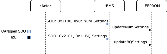
The “Actor” in the sequence diagram is any system set up for sending the settings over CANopen. This could be anything from the GUB, Vector CAN, etc. The Actor starts by sending over the number of settings via an SDO request to index 0x2100 and sub-index 0x0. This transfer is an expedited SDO request with a 2 byte value. The BMS will then save the new number of settings into EEPROM.
Next, the Actor sends over the BQ settings via a segmented SDO request to index 0x2100 and sub-index 0x1. The settings will be formatted following the convention above, the Actor will continue sending the bytes making up the array of settings until all settings have been transferred. As the settings are received, the BMS will store the results into EEPROM.
UART
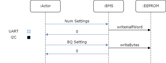
The “Actor” in the sequence diagram is normally your laptop, but it can be any device with a UART. The Actor starts the transfer sequence by transmitting the number of settings to be sent in raw bytes, not as ascii characters. Then, the BMS will react by writing the number received to the EEPROM and responding with a 0 byte.
When the Actor receives a 0 byte, it should transmit the first setting. The BMS will then receive and write the first setting and transmit another 0 byte. The Actor will continue sending settings, each acknowledged with a 0 byte until all settings have been transferred.
For instructions on how to transfer the settings, refer to this documentation.